1. Introduction
The Valve-Regulated Lead-Acid (VRLA) battery is the standard energy storage solution for modern industrial applications, including telecommunications, data centers, and utility substations. Unlike traditional "flooded" lead-acid designs, VRLA batteries utilize an immobilized electrolyte system—held in place by an Absorbent Glass Mat (AGM) or a gel agent —which allows the battery to operate in various orientations without leaking [1].
A defining feature of the VRLA design is the oxygen recombination cycle. During charging, oxygen generated at the positive plate migrates through the separator to the negative plate, where it recombines to form water. This process significantly reduces gas emission and eliminates the need for water addition, leading to the designation "maintenance-free" [1]. However, this term is misleading regarding the battery's longevity. As noted in industry literature, a lead-acid battery is fundamentally an electrochemical plant that functions by slowly consuming itself [1].
While VRLA batteries offer operational flexibility, they are more sensitive to environmental conditions than flooded counterparts. They possess unique failure modes—such as thermal runaway and dry-out—that facility operators must understand to prevent system failure.
2. The Physics of Aging: Critical Operating Parameters
The degradation rate of a VRLA battery is governed primarily by two external variables: ambient temperature and float voltage. These factors dictate the rate of the internal chemical reactions that store energy, as well as the parasitic reactions that degrade the cell.
2.1 Temperature Dependence
Temperature is the dominant accelerant of battery aging. Manufacturers typically rate VRLA battery performance and design life at a standardized temperature of 77°F (25°C) [1].
High Temperature Effects: The relationship between temperature and aging follows the Arrhenius equation. For every 18°F (10°C) increase in operating temperature above the standard 77°F (25°C), the battery’s expected service life is reduced by approximately 50%. For example, a battery with a 10-year design life operating continuously at 95°F (35°C) will likely fail within five years [2].
Monitoring Note: High temperatures also dramatically increase float current. At 113°F (45°C), a battery will draw significant excess current, which drives the oxygen recombination process. Since recombination is exothermic (heat-generating), this creates a risk of thermal instability [1]. Monitoring float current allows for detection of the specific current rise before temperature spirals out of control.
Low Temperature Effects: Conversely, operating below 77°F slows internal chemical kinetics. While this may retard grid corrosion, it creates a different set of risks. At lower temperatures (e.g., 60°F or 15°C), the standard float voltage may not generate enough current to overcome the battery's self-discharge rate. This leads to the gradual sulfation of the negative plates, where soft lead sulfate hardens into stable crystals that cannot be recharged, resulting in permanent capacity loss [1].
2.2 Float Voltage and Plate Polarization
VRLA batteries typically spend the majority of their service life on "float charge"—a constant voltage supply designed to maintain the battery at 100% State of Charge (SOC) [1].
The voltage applied to the cell supports three distinct processes:
- Compensating for self-discharge.
- Supporting positive grid corrosion (a natural side-effect).
- Driving the oxygen recombination cycle.
The Polarization Challenge: When a charging current is applied, the voltage of the plates rises above their open-circuit potential; this difference is known as polarization. In VRLA batteries, the positive plate polarization is inherently higher than in flooded cells [1].
Operators must maintain float voltage within a specific window (typically 2.25 to 2.30 volts per cell at 77°F).
- Insufficient Voltage: If the voltage is too low, the battery fails to recharge fully, leading to negative plate sulfation.
- Excessive Voltage: If the voltage is too high, it drives excessive polarization at the positive plate. This accelerates the oxidation of the lead grid and increases the rate of electrolyte water loss through venting.
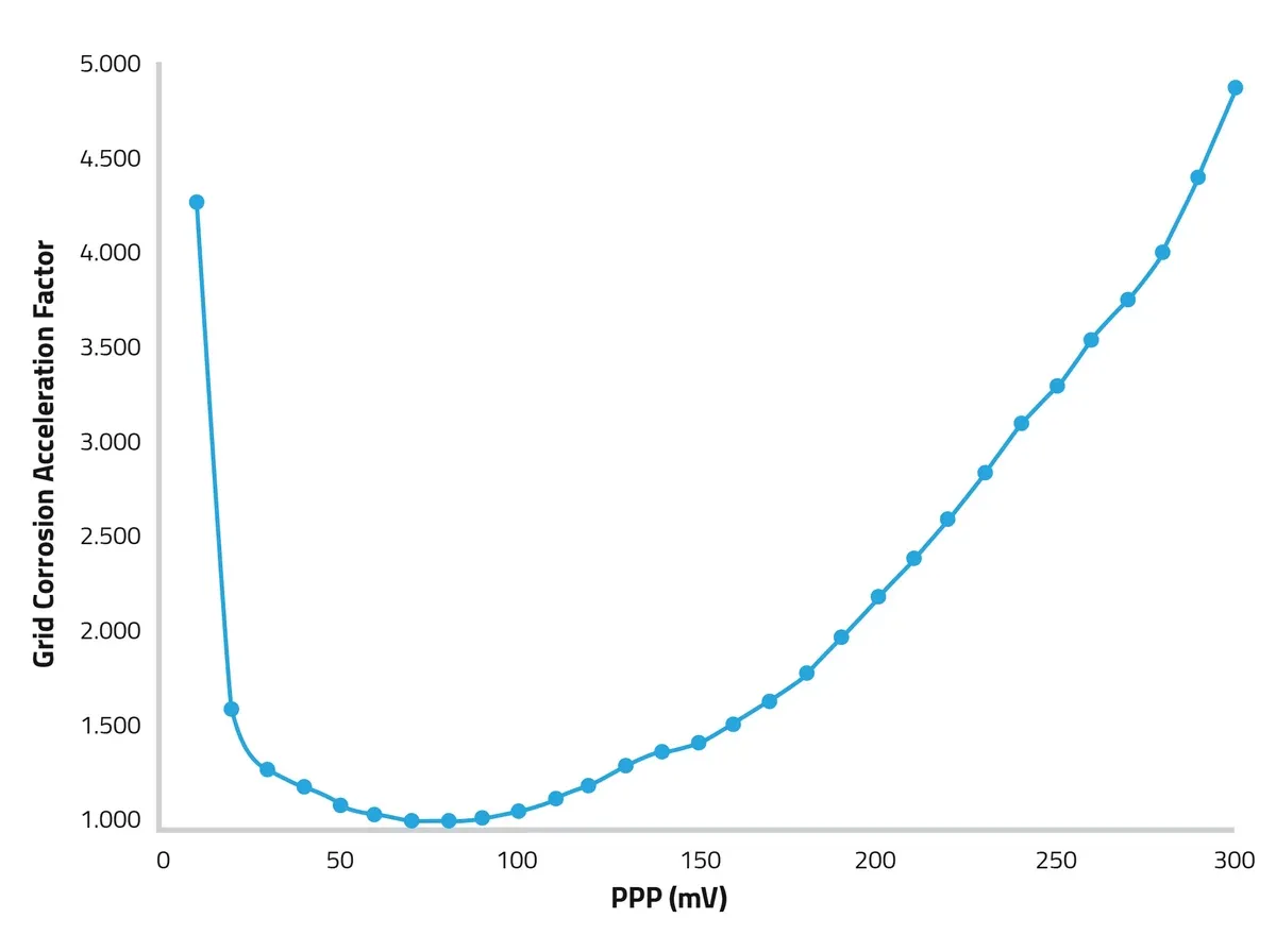 Figure 4: Positive grid Corrosion Acceleration vs (+) Plate Polarization
3. Primary Failure Mechanisms
Understanding how the operating parameters above physically destroy the battery components helps in diagnosing failure.
3.1 Positive Grid Corrosion
Positive grid corrosion is the primary life-limiting factor for lead-acid batteries. The positive grid, made of lead alloy, conducts current and supports the active material. Under float charge, this lead slowly oxidizes (corrodes).
As the lead corrodes, it converts to lead oxides which occupy a larger volume than the original metal. This phenomenon, known as "grid growth," causes the internal structure to expand. In severe cases, this expansion can crack the battery container or separate the grid from the active material, destroying the electrical continuity [2]. This physical separation causes a measurable rise in internal resistance (Ohmic value), which is a key metric for predictive maintenance.
3.2 Electrolyte Dry-Out
Unlike flooded batteries, VRLA cells cannot be topped up with water. They rely on the efficiency of the recombination cycle to retain moisture. However, under conditions of overcharging or high heat, the rate of gas generation exceeds the rate of recombination. The internal pressure rises until the one-way pressure relief valves open, venting hydrogen and oxygen into the atmosphere.
This loss is irreversible. As the electrolyte volume decreases (dry-out), the internal resistance of the cell increases, and the battery loses its ability to support high-current discharges.
3.3 Thermal Runaway
Thermal runaway is a catastrophic failure mode specific to VRLA technologies. It occurs when the heat generated within the battery exceeds its ability to dissipate that heat into the environment.
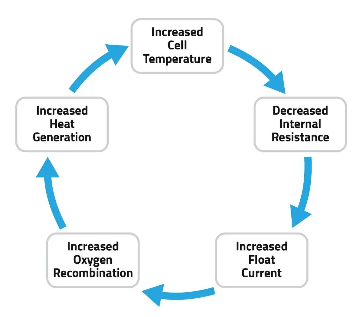 Figure 5: Thermal Runaway
The mechanism is a positive feedback loop:
- High temperature or voltage causes increased float current.
- Excess current drives the oxygen recombination reaction.
- Recombination is exothermic, releasing heat.
- The internal temperature rises further, lowering the battery's internal resistance.
- The battery draws even more current, restarting the cycle with greater intensity [1].
If unchecked, thermal runaway results in the melting of the battery jar, emission of toxic hydrogen sulfide gas, and potential fire.
Monitoring Note: CellSPY utilizes a dual prong approach to catch thermal runaway conditions:
- Float current is continuously measured and the system alarms when it increases by 3x the baseline
- Individual cell/jar temperatures are measured and each is compared against the ambient temperature
If a relay is included, the system can trip the breaker and automatically disconnect the string from the charger to prevent the thermal runaway from accelerating further.
4. Diagnostics and Troubleshooting
Because VRLA batteries are sealed, operators cannot measure specific gravity to determine health. Diagnostics must rely on external electrical measurements and visual inspections.
4.1 Visual Inspection
Visual cues often indicate that a battery has already failed or is in a dangerous state.
- Swollen Containers: A permanently deformed or "puffed" plastic case indicates the battery has suffered from thermal runaway and excessive internal pressure. These units must be replaced immediately [2].
- Terminal Corrosion: White or gray deposits around terminals suggest electrolyte is wicking through the seal. This can corrode the copper inter-unit connectors.
- Melted Grease: Connection points are often coated with protective grease. If this grease appears melted or flows onto the cover, the connection has overheated, likely due to high electrical resistance caused by loose hardware [3].
4.2 Electrical Measurements
- Float Current Monitoring: Monitoring the current flowing into a fully charged string is a highly effective diagnostic.
- High Current: Current exceeding recommended values (e.g., >3.0 mA per Ah at 77°F) usually indicates a shorted cell or the onset of thermal runaway [2].
- Zero Current: Indicates an open circuit within the string, often caused by a fractured strap or loose connection.
- Impedance and Conductance: As a battery ages, its internal conductive path degrades. A 20% increase in resistance (or decrease in conductance) is a warning sign. A 50% change from the baseline value typically indicates the battery has degraded significantly and requires replacement [2].
- AC Ripple: Chargers with degraded capacitors may pass AC ripple voltage to the battery. If AC ripple exceeds 0.5% RMS (or 1.5% peak-to-peak) of the DC float voltage, it causes internal heating that accelerates plate deterioration [2].
Monitoring Note: CellSPY automatically includes these default threshold limits, and users can modify them as needed.
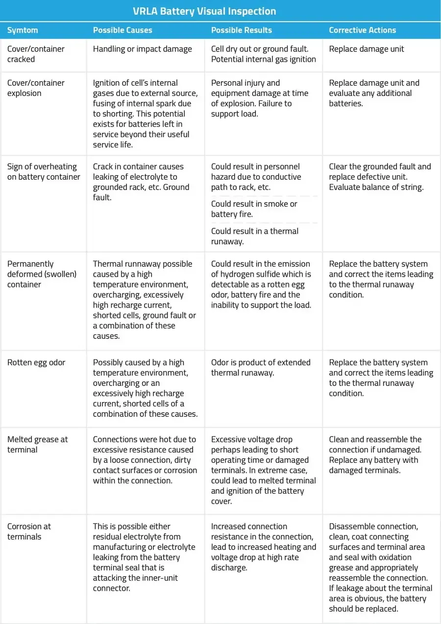 Source: VRLA Battery Symptoms and Solutions, Hitachi Chemical
4.3 Capacity Testing
While impedance and voltage measurements provide trending data, they do not perfectly correlate with runtime. The only definitive method to verify battery health is a load test. A battery is defined as failed when it can only deliver 80% of its rated capacity [2]. For example, if a battery is rated to provide 100 Amps for one hour, it should be replaced once it can only sustain that load for 48 minutes.
Monitoring Note: CellSPY includes a capacity reporting feature so that when the battery is discharged, users can generate capacity reports that give them individual cell/jar capacity as well as string capacity.
5. Mitigation Strategies
To extend the service life of VRLA systems, operators should implement the following maintenance protocols:
- Temperature Compensation: Modern chargers should utilize temperature compensation. This feature automatically adjusts the float voltage inversely to ambient temperature—lowering voltage as temperature rises to prevent runaway, and raising it as temperature falls to prevent sulfation [1].
- Torque Verification: Thermal cycling can cause connection hardware to loosen over time. Annual retorquing to manufacturer specifications is required to prevent highresistance heating [2].
- Voltage Accuracy: The rectifier must maintain float voltage control with an accuracy of ±1% to keep the battery within the narrow window that balances corrosion against sulfation [1].
- Continuous Monitoring: Implementing a system to track individual cell/jar voltage, temperature, resistance, strap resistance, ripple voltage, and string float/charge/discharge current, ensures that these mitigation strategies are actually working 24/7/365
6. Conclusion
VRLA batteries provide essential backup power capabilities but require strict environmental management to function reliably. They are subject to specific aging mechanisms—primarily positive grid corrosion and electrolyte dry-out—that are significantly accelerated by improper temperature and voltage control. By implementing rigorous monitoring of impedance, float current, and physical condition, operators can mitigate the risks of catastrophic failure and ensure system availability.
References
[1] J. Jergl, B. Cole, and S. Purcell, "Real World Effects on VRLA Batteries in Float Applications," GNB Technologies, 1996 IEEE.
[2] C&D Technologies, Inc., "10 Year VRLA Battery Periodic Maintenance Instructions," Technical Bulletin 41-7546, Feb. 2013.
[3] Hitachi Chemical Energy Technology Co., Ltd., "VRLA Battery Symptoms and Solutions," Technical Inspection Guide.


